Language
Injection molding machine (injection molding machine, i […]
Injection molding machine (injection molding machine, injection machine) is the main molding equipment that uses plastic molding dies to make thermoplastic or thermosetting materials into various shapes and plastic products. Divided into vertical, horizontal and all-electric. Today I will work with you to understand the various components that make up the injection molding machine. The injection molding machine can be roughly divided into an injection part and a clamping part in terms of mechanical structure. The function of the injection part is to melt and inject the plastic into the mold cavity, and the function of the clamping part is to control various actions such as opening and closing of the mold and ejecting the product.
1, injection part
There are two main types of injection part: piston type and reciprocating screw type. Piston-type injection molding machines are rare now, so I won’t introduce them here.
The reciprocating screw injection molding machine melts and mixes solid plastic particles (or powder) through the rotation of the screw in the heating barrel, and squeezes it into the cavity at the front end of the barrel. Then the screw moves forward in the axial direction to remove the plastic in the cavity. The melt is injected into the mold cavity. During plasticization, the plastic is compacted in the screw groove under the push of the screw ridge, and receives the heat transferred from the barrel wall. In addition, the plastic and the plastic, the plastic and the barrel and the surface of the screw friction and heat, the temperature gradually rises High to melting temperature. The melted plastic is stirred and further mixed by the screw, and enters the front of the barrel along the screw groove and pushes the screw back. Kangda screw
The plasticization-related components of the injection part mainly include: screw, barrel, shunt shuttle, check ring, nozzle, flange, hopper, etc. The following is an explanation of its role and influence in the plasticizing process.
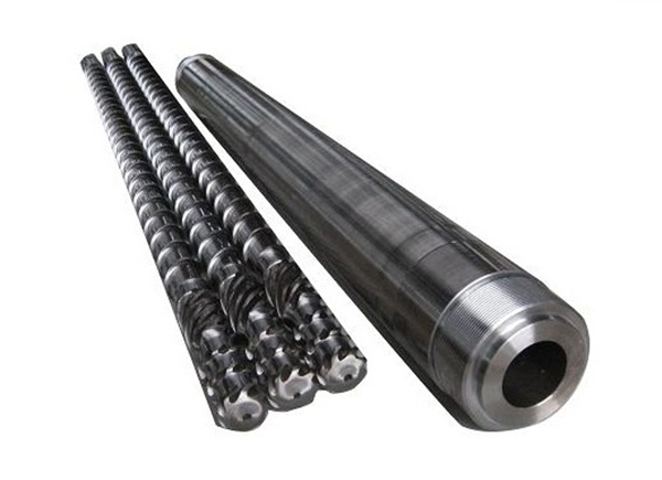
Screw is an important part of injection molding machine. Its function is to transport, compact, melt, stir and press plastic. All of this is accomplished by the rotation of the screw in the barrel. When the screw rotates, the plastic will generate friction and mutual movement on the inner wall of the barrel, the bottom surface of the screw groove, the screw edge advancement surface, and the plastic and the plastic. The advancement of plastic is the result of this combination of movements, and the heat generated by friction is also absorbed to increase the temperature of the plastic and melt the plastic. The structure of the screw will directly affect the extent of these effects.
Ordinary injection screw structure is also designed to better improve the plasticization quality as a separate screw, barrier screw or split screw.
The structure of the barrel actually means a round tube with a discharge opening in the middle.
In the plasticization process of plastics, the driving force for advancement and mixing is derived from the relative rotation of the screw and barrel. According to the different forms of plastic in the screw groove, the screw is generally divided into three sections: solid conveying section (also called feeding section), melting section (also called compression section), and homogenizing section (also called metering section).
In the textbooks on plasticization, the plastic in the solid conveying section of the screw is regarded as a solid bed with no mutual movement between plastic particles, and then passes through the solid bed and the barrel wall, and the screw edge propelling surface and the screw groove. The ideal state of surface movement and friction is calculated to determine the speed at which the plastic is conveyed forward. This is quite different from the real situation, and it cannot be used as a basis to analyze the feeding situation of plastic particles of different shapes. If the plastic particles are not large, they will stratify and roll when they are pulled forward by the inner wall of the barrel, and will gradually be compacted to form a solid plug. When the diameter of the expected material particles is similar to the depth of the screw groove, most of their motion trajectories are linear motion along the radial direction of the screw groove plus linear motion at an angle. When the particles are large, the arrangement of the plastic in the screw groove is very loose, so the conveying speed is also slow. When the particles are large enough to a certain extent, when they enter the compression section and their diameter is greater than the depth of the screw groove, the plastic will be stuck between the screw and the barrel. If the forward pulling force is not enough to overcome the need to flatten the plastic particles If the force is higher, the plastic will be stuck in the screw groove and will not push forward.
When the plastic is close to its melting point, the plastic in contact with the barrel has begun to melt to form a layer of molten film. When the thickness of the melt film exceeds the gap between the screw and the barrel, the top of the screw ridge scrapes the melt film radially from the inner wall of the barrel to the root of the screw ridge, thereby gradually converging into a vortex-like flow zone on the advancing surface of the screw ridge—— Molten pool.
Due to the gradual shallowness of the groove depth in the melting section and the extrusion of the molten pool, the solid bed is squeezed to the inner wall of the barrel, which accelerates the heat transfer process from the heat barrel to the solid bed. At the same time, the rotation of the screw causes shearing of the melt film between the solid bed and the inner wall of the barrel, thereby melting the solid at the interface between the melt film and the solid bed. As the spiral of the solid bed moves forward, the volume of the solid bed gradually decreases, while the volume of the molten pool gradually increases. If the thickness of the solid bed decreases at a rate lower than the speed at which the depth of the screw groove becomes shallow, the solid bed may partially or completely block the screw groove, causing fluctuations in plasticization, or a sharp increase in frictional heat due to excessive local pressure. Local overheating occurs.
In the homogenization section of the screw, the solid bed has been broken due to its small volume, forming small solid particles dispersed in the molten pool. These solid particles are melted by friction and heat transfer with the melt surrounding the coating. At this time, the function of the screw is mainly to stir the plastic melt to make it evenly mixed. The velocity distribution of the melt ranges from the highest speed close to the barrel wall to the lowest speed close to the bottom of the screw groove. If the groove depth is not large and the melt viscosity is high, then the friction between the melt molecules will be very intense.
Due to the large differences in the melting speed, melt viscosity, melting temperature range, viscosity of various plastics to temperature and shear rate, the corrosiveness of pyrolysis gases, and the coefficient of friction between plastic particles, it is common in the general sense. When the screw is processing some plastics with outstanding melt characteristics (such as Pc, PA, polymer ABS, PP-R, PVC, etc.), a certain section of shear heat will be too high. This phenomenon can generally be reduced by reducing The screw speed is eliminated. But this is bound to affect production efficiency. In order to achieve efficient plasticization of these plastics, many companies have successively developed special plasticizing screws and barrels for these plastics. The main problems that these special screws and barrels are designed for are the solid friction coefficient, melt viscosity, and melting speed of the above plastics.
2. Shunt shuttle (with rubber head)
The diverter shuttle is a torpedo-shaped part mounted on the front end of the screw. The function of the shunt shuttle in the plasticization of plastics is mainly to shunt and mix the plastic melt, so that the melt is further mixed evenly. At the same time, the shunt shuttle also has the function of limiting the position of the anti-return ring during plasticization.
In order to further strengthen the mixing effect, it is recommended to adopt a barrier type mixing structure on an injection molding machine with a clamping force of over 250 tons. The shunt shuttle. Not only can the uniformity of the color of the product be improved, but also the mechanical strength of the product can be higher.
3. Anti-reverse ring (over the rubber ring)
As the name suggests, the role of the anti-reversal ring is to prevent the reverse. It is a part that prevents the plastic melt from leaking back during injection. When working, the non-return ring and the non-return washer (over-rubber washer) contact to form a closed structure to prevent the plastic melt from leaking. The working principle of the non-return ring.
The precision of the weight of an injection molded product of an injection molding machine has a great relationship with the speed of the anti-reverse ring anti-reverse movement. The speed of a non-return ring action response is determined by its non-reverse movement stroke, seal pressing time, time to leave the shunt shuttle and other factors. We have tried a variety of non-return ring structures and parts parameters, and finally determined the optimal non-reverse surface parameters, the non-reverse ring and the shunt shuttle fitting parameters, the non-reverse ring and the barrel clearance parameters through experiments. It can easily achieve high-precision injection volume control.
4. Nozzle
The nozzle is the transition part connecting the barrel and the mold. When injecting, the melt in the barrel is pushed by the screw to inject the mold with high pressure and rapid flow through the nozzle. Therefore, the structure and form of the nozzle, the size of the nozzle, and the manufacturing accuracy will affect the pressure and temperature loss of the melt, the range, the pros and cons of the feeding effect, and whether the phenomenon of "salivation" occurs. There are many types of nozzles currently in use, and they all have their scope of application. Only the three most used are discussed here.
(1) Straight-through nozzle This nozzle has a short tube shape. When the melt flows through this nozzle, the pressure and heat loss are very small, and it is not easy to produce stagnation and decomposition, so the outside of it is generally not attached with a heating device. However, due to the short nozzle body, the length that can be extended into the hole of the fixed template is limited, so the main runner of the mold used is long. In order to compensate for this defect, the length of the nozzle is increased, which becomes an improved type of the straight-through nozzle, also known as the extended nozzle. This nozzle must be equipped with a heating setting. In order to filter out solid impurities in the molten material, a filter screen can also be installed in the nozzle. The above two nozzles are suitable for processing high-viscosity plastics, and salivation will occur when processing low-viscosity plastics.
(2) Self-locking nozzle During the injection process, in order to avoid the salivation or retraction of the melt, it is necessary to temporarily block the nozzle channel and adopt the self-locking nozzle. Among the self-locking nozzles, the spring type and the needle valve type are the most widely used. This type of nozzle relies on the spring to press the valve core in the nozzle to achieve self-locking. When injecting, the valve core is pushed open by the high pressure of the melt, and the melt is injected into the mold. When melting glue, the valve core is reset and self-locked under the action of spring. Its advantage is that it can effectively prevent the "salivation" phenomenon when injecting low-viscosity plastics, is convenient to use, and has a significant self-locking effect. However, the structure is very complicated, the injection pressure loss is large, the shooting range is short, the feeding effect is small, and the requirements for the spring are high.
The lever needle valve nozzle is the same as the self-locking nozzle. It is also a kind of temporary opening and closing of the nozzle channel during the injection process. It uses an external hydraulic system to control the opening and closing valve of the linkage mechanism through a lever. Core. When in use, the operated hydraulic system can open the valve core accurately and timely according to the needs, and has the advantages of convenient use, reliable self-locking, low pressure loss, accurate measurement, etc. In addition, it does not use a spring, so there is no need to replace the spring. The main disadvantage is that the structure is more complicated and the cost is higher.
During injection, the plastic melt is pushed by the screw and flows through the nozzle at a very high shear speed into the cavity. Under this high-speed shear, the melt temperature rises rapidly. Especially for high viscosity PVC, PP-R, PMMA, PC, high impact ABS, etc., too small nozzle hole diameter will cause high temperature decomposition of plastic. For thin-walled precision products that are difficult to fill, a nozzle with a longer range should be used, and for thick-walled products, a nozzle with a good plasticizing effect is required. In addition, for some plastics with very low melt viscosity (such as PA, etc.), a self-locking nozzle with anti-salivation function is required.
In many machines, in addition to general-purpose nozzles for general viscosity, there are also special nozzles such as self-locking nozzles, PVC nozzles, PMMA nozzles and so on. If necessary, they can also provide longer range for thin-walled nozzles. Dedicated nozzle for products.
5. Flange
Flange is the part that connects the nozzle and the barrel? It only serves as a channel in the plastic injection process. If there is a large gap or groove on the joint surface of the flange and the nozzle or the flange and the barrel, the black spots of the product will appear due to the decomposition of the plastic in the gap or groove for too long.
6. Feeding hopper
The feeding hopper is a part that stores plastic raw materials, and some add heating and blowing devices to the feeding hopper to make a drying hopper. The shape of the hopper is generally a lower cone shape and an upper cylindrical shape. The cone-shaped cone slope has different optimal values for plastic parts with different particle sizes, different particle shapes, and different friction coefficients and adhesion coefficients between particles. Otherwise, the storage capacity of the hopper is wasted or the feeding is not smooth. Or the phenomenon of "bridging" or "funneling into tubes" where the material is not discharged at all.
The reason for the "bridging" sign is that the plastic particles form an open bridge between the small cones that can support the material above it. It is easier to produce larger particles and irregular shapes of recycled materials. "Funnel into tube" is because the lower particles are not enough to pull the adjacent particles to move together, which is often produced when the plastic particle size is small. The general solution is to install a vibration assembly on the hopper or reduce the cone slope. If the heat on the barrel is reported to the hopper to make the temperature of the hopper too high, the plastic particles will harden or stick into blocks, which is more likely to form "bridging" or obstruction.
https://www.txscrew.com/